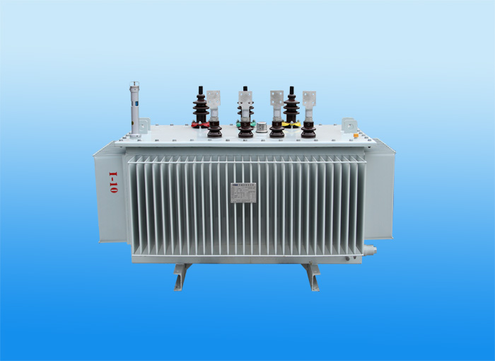

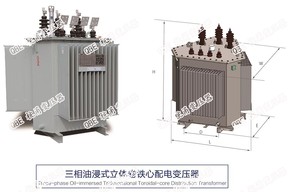
(C) The design and manufacturing of the three-phase amorphous alloy distribution transformers produced by the company comply with IEC60076, GB1094 and GB/T25446 standards. It is a new type of transformer with amorphous metal as the core material. It has high saturation magnetic induction strength, low coercive force, ultra-low loss, low exciting current and good temperature stability.
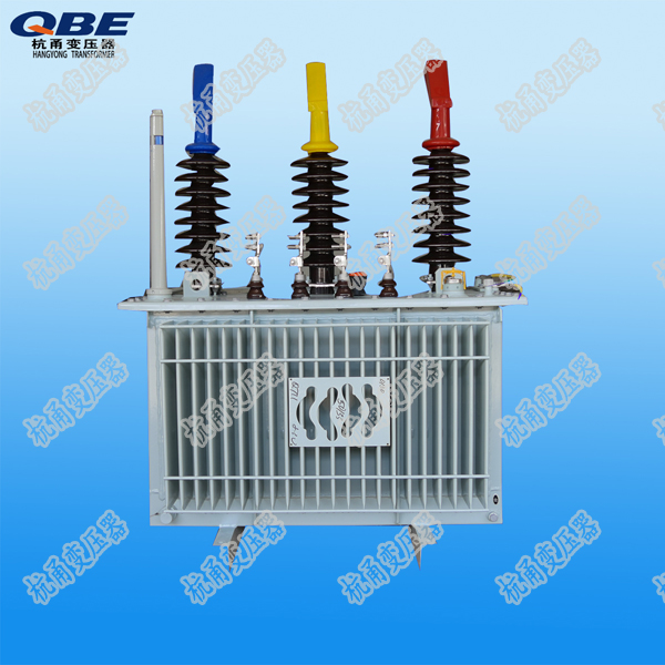
The product adopts a three-phase, four-frame and five-column structure. The core material is Hitachi 2605SA1, and the wires are oxygen-free copper. The connection group is Dyn11, which is conducive to reducing the impact of power grids and improving power supply quality. The oil tank adopts a corrugated oil tank sealed structure. The transformer bushing is routed on the upper part of the tank cover. The pressure protection device operates reliably and is maintenance-free. Compared with S11 transformers, amorphous alloy transformers reduce no-load losses by about 70%, and no-load current by about 70%. The energy-saving effect is very obvious. It is a green and environmentally friendly, efficient energy-saving transformer.
Main technical indicators:
S(B)H15Main technical parameters of series amorphous alloy transformers | |||||||||||||||
Rated capacity (kVA) | High-voltage combination and tapping range | connection group symbol | no-load loss (W) | load loss (W) | no-load current (%) | short-circuit impedance (%) | Body (kg) | Oil weight (kg) | Total weight (kg) | Overall size (mm) | |||||
High voltage (kV) | Tap range (%) | Low voltage (kV) | long | Width | High | gauge | |||||||||
30 | 6 6.3 10 10.5 11 | ±5 ±2×2.5 | 0.4 | Dyn11 | 33 | 600 | 1.7 | 4.0 | 210 | 90 | 365 | 955 | 638 | 812 | 550*550 |
50 | 43 | 870 | 1.3 | 270 | 100 | 445 | 1005 | 663 | 822 | 550*550 | |||||
80 | 60 | 1250 | 1.1 | 370 | 130 | 575 | 1120 | 678 | 872 | 550*550 | |||||
100 | 75 | 1500 | 1.0 | 385 | 135 | 605 | 1130 | 674 | 887 | 550*550 | |||||
125 | 85 | 1800 | 0.9 | 450 | 160 | 710 | 1120 | 702 | 933 | 550*550 | |||||
160 | 100 | 2200 | 0.7 | 545 | 165 | 820 | 1233 | 848 | 879 | 660*660 | |||||
200 | 120 | 2600 | 0.7 | 625 | 180 | 930 | 1328 | 903 | 904 | 660*660 | |||||
250 | 140 | 3050 | 0.7 | 740 | 235 | 1085 | 1348 | 863 | 965 | 660*660 | |||||
315 | 170 | 3650 | 0.5 | 840 | 230 | 1255 | 1518 | 943 | 959 | 660*660 | |||||
400 | 200 | 4300 | 0.5 | 1010 | 290 | 1505 | 1698 | 1023 | 994 | 660*660 | |||||
500 | 240 | 5150 | 0.5 | 1145 | 305 | 1685 | 1682 | 1022 | 1055 | 660*660 | |||||
630 | 320 | 6200 | 0.3 | 4.5 | 1395 | 355 | 2015 | 1812 | 1012 | 1101 | 820*820 | ||||
800 | 380 | 7500 | 0.3 | 1765 | 410 | 2490 | 1877 | 1087 | 1198 | 820*820 | |||||
1000 | 450 | 10300 | 0.3 | 2370 | 705 | 3200 | 2155 | 1260 | 1335 | 820*820 | |||||
*The above data is for reference only, and the company reserves the right to change the data.
(C) The design and manufacturing of the three-phase amorphous alloy distribution transformers produced by the company comply with IEC60076, GB1094 and GB/T25446 standards. It is a new type of transformer with amorphous metal as the core material. It has high saturation magnetic induction strength, low coercive force, ultra-low loss, low exciting current and good temperature stability.
The product adopts a three-phase, four-frame and five-column structure. The core material is Hitachi 2605SA1, and the wires are oxygen-free copper. The connection group is Dyn11, which is conducive to reducing the impact of power grids and improving power supply quality. The oil tank adopts a corrugated oil tank sealed structure. The transformer bushing is routed on the upper part of the tank cover. The pressure protection device operates reliably and is maintenance-free. Compared with S11 transformers, amorphous alloy transformers reduce no-load losses by about 70%, and no-load current by about 70%. The energy-saving effect is very obvious. It is a green and environmentally friendly, efficient energy-saving transformer.
Main technical indicators:
S(B)H15Main technical parameters of series amorphous alloy transformers | |||||||||||||||
Rated capacity (kVA) | High-voltage combination and tapping range | connection group symbol | no-load loss (W) | load loss (W) | no-load current (%) | short-circuit impedance (%) | Body (kg) | Oil weight (kg) | Total weight (kg) | Overall size (mm) | |||||
High voltage (kV) | Tap range (%) | Low voltage (kV) | long | Width | High | gauge | |||||||||
30 | 6 6.3 10 10.5 11 | ±5 ±2×2.5 | 0.4 | Dyn11 | 33 | 600 | 1.7 | 4.0 | 210 | 90 | 365 | 955 | 638 | 812 | 550*550 |
50 | 43 | 870 | 1.3 | 270 | 100 | 445 | 1005 | 663 | 822 | 550*550 | |||||
80 | 60 | 1250 | 1.1 | 370 | 130 | 575 | 1120 | 678 | 872 | 550*550 | |||||
100 | 75 | 1500 | 1.0 | 385 | 135 | 605 | 1130 | 674 | 887 | 550*550 | |||||
125 | 85 | 1800 | 0.9 | 450 | 160 | 710 | 1120 | 702 | 933 | 550*550 | |||||
160 | 100 | 2200 | 0.7 | 545 | 165 | 820 | 1233 | 848 | 879 | 660*660 | |||||
200 | 120 | 2600 | 0.7 | 625 | 180 | 930 | 1328 | 903 | 904 | 660*660 | |||||
250 | 140 | 3050 | 0.7 | 740 | 235 | 1085 | 1348 | 863 | 965 | 660*660 | |||||
315 | 170 | 3650 | 0.5 | 840 | 230 | 1255 | 1518 | 943 | 959 | 660*660 | |||||
400 | 200 | 4300 | 0.5 | 1010 | 290 | 1505 | 1698 | 1023 | 994 | 660*660 | |||||
500 | 240 | 5150 | 0.5 | 1145 | 305 | 1685 | 1682 | 1022 | 1055 | 660*660 | |||||
630 | 320 | 6200 | 0.3 | 4.5 | 1395 | 355 | 2015 | 1812 | 1012 | 1101 | 820*820 | ||||
800 | 380 | 7500 | 0.3 | 1765 | 410 | 2490 | 1877 | 1087 | 1198 | 820*820 | |||||
1000 | 450 | 10300 | 0.3 | 2370 | 705 | 3200 | 2155 | 1260 | 1335 | 820*820 | |||||
*The above data is for reference only, and the company reserves the right to change the data.